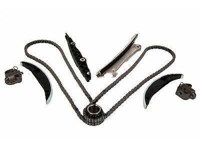
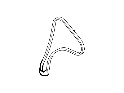
At least, to perform these operations, particular tools such as camshaft position tool (303-1552), timing of VCT locking tool (303-1097), crankshaft pulley alignment tool (303-1550), the flywheel locking tools (303-393A and 303-393-02) and timing pin (303-748) are needed. The following are the tools you should have before commencing the job. This is in contrast to the other three types in which only clockwise rotation of the crankshaft is allowed. First, get rid of the negative terminal of the battery, then free the right-side lug nuts of the wheel, lift the car and then, finally, remove the wheel. Next, pop the right-side inner fender splash shield and under-vehicle splash shield, add the engine cover, CAC inlet and outlet tubes and bracket if any. Remove the connectors for the powertrain control module and main engine harness, and the coolant expansion tank, air filler housing inlet and outlet hoses, turbocharger inlet hose, and unbolt the water pump pulley. Take off the drive belt, the right-side drive axle, the intermediate shaft bearing support bracket, the starter motor and the alternator. Place a jack underneath the engine oil pan so the right-side mount weight is relieved, then remove the right-side engine mount. Here, now that the mount has been taken off, lift the engine slightly and take the drive belt tensioner off also. Pull out the vacuum line retainer bracket on rear side of cylinder head and then turn counter clockwise and take away the cover stud bolt. Pull the side inspection cover to the side to unlock the clip, retract the cover and take off the side timing cover. The water pump pulley mounting bolts and pulley have to be removed next; in addition, the timing cover fasteners and harness fasteners have to be unbolted from the cover. Pull the top part of the cover downwards and remove it in the forward and backward direction parallel to the engine. Take off the valve cover and the bracket of the right side engine mount. You can now then place an engine support fixture and make sure that it is well fastened on the cylinder head. Turn the crankshaft further until the camshaft phaser marks are in line with the '11 o'clock' mark and then, unscrew the TDC timing hole plug and install the timing pin in it. Turn the crankshaft clockwise slowly until you can feel the crankshaft balance weight hitting the timing pin thus showing you that the engine is at TDC. This should be done with considerable care and the locks that are used to hold the flywheel in place must be firmly fixed into position. Locate the crankshaft pulley bolt and pulley and then, loosen it and then turned it until the VCT sprocket timing marks are at 12 o'clock. Place the VCT locking tool over the two camshafts so that it grips the VCT sprocket in both cases. Turn anti-clockwise until the tab fits into the tensioner body then tighten using a drill bit or Allen key. Examine the timing belt on the engine and if you see any trace of wear replace it. Place it over the crankshaft sprocket first before the intake and exhaust camshaft sprockets and over the tensioner. Take out the drill bit or Allen key from the tensioner so that the latter can stretch and retract to eliminate slack. Put the crankshaft pulley alignment tool where the CKP sensor was located and fit the crankshaft pulley and bolt. Revolve the positioner-counter to make it '0' before removing the alignment tool and tightening the crankshaft bolt. Pull out the VCT locking tool, the flywheel locking tools and the timing pin from the cylinder block. Slowly rotate the crankshaft 45 degrees clockwise in a locking position 1-3/4 turns and align the timing pin available on it, rotate it further till the crankshaft balance weight touches the pin. Align the VCT sprocket timing marks to the 12 o'clock position and fit the locking tool of the VCT. If the tool can be installed, the timing belt is correctly installed If the timing belt cannot be installed the above diagram shows that it is inserted incorrectly. Replacement of the crankshaft position sensor, the engine mount bracket nuts and bolts then tightening of the screws. Last but not the least, pick up the timing cover and fasten the screws to complete the repair sequence in a backward way of the same processes.
Posted by FordPartsGiant Specialist 

