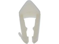
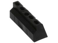
Make sure this part fits

Ford F4UZ-12B579-A Sensor Assembly

1994-1996 Ford F4UZ12B579A

Customer Questions & Expert Answers (3)
Ford F4UZ-12B579-A Sensor Assembly
  • Part Description
    SENSOR ASY
  • Manufacturer
    Ford
  • Manufacturer's Notes
    This part is discontinued.
Make sure this part fits
$0.00Currently Unavailable

Due to manufacturer supply shortage, this item isn’t currently available for ordering.

  • Related Parts
  • Product Specifications
  • Vehicle Fitment
  • Customer Questions & Expert Answers
  • Product Specifications

    BrandGenuine Ford
    Manufacturer Part NumberF4UZ-12B579-A, F4UZ12B579A
    Part DescriptionSENSOR ASY
    Item Dimensions5.8 x 3.6 x 4.0 inches
    ConditionNew
    Fitment TypeDirect Replacement
    ManufacturerFord
    SKUF4UZ-12B579-A
    WarrantyThis genuine Ford part is guaranteed by Ford's factory warranty.
    Shipping & ReturnShipping Policy Return Policy
    Warning: California’s Proposition 65
  • Vehicle Fitment

    Year Make Model Engine Important vehicle option details
    1994-1996 Ford Bronco8 Cyl 5.0L, 8 Cyl 5.8L3AT C6, 4AT A4LD, 4AT E4OD, 5MT
    1995 Ford E-1508 Cyl 5.0L, 8 Cyl 5.8L3AT C6, 4AT 4R70W, 4AT 4R75W, 4AT E4OD
    1995 Ford E-2508 Cyl 5.8L3AT C6, 4AT E4OD
    1995 Ford E-350/E-350 Super Duty8 Cyl 5.8L3AT C6, 4AT E4OD
    1994-1995 Ford F-1508 Cyl 5.0L, 8 Cyl 5.8L3AT C6, 4AT 4R70W, 4AT 4R75W, 4AT E4OD, 4MT, 5MT
    1994-1995 Ford F-2508 Cyl 5.0L, 8 Cyl 5.8L3AT C6, 4AT E4OD, 4MT, 5MT
    1995 Ford F-3508 Cyl 5.8L3AT C6, 4AT E4OD
  • Customer Questions & Expert Answers

    Q:
    Is the the correct part for the attached VIN? Posted by FordPartsGiant Specialist
    A:
    You can Select Your Vehicle to check if F4UZ-12B579-A fits your vehicle.
    Posted by FordPartsGiant Specialist
    Q:
    How to check Brake Light Switch,Coolant Temperature Sensor,EGR Valve Position Sensor,Intake Manifold Temperature Sensor,Knock Sensor,MAP Sensor,Mass Air Flow Sensor,Oxygen Sensors,Throttle Position Sensor on Ford F-250? Posted by Customer
    A:
    When working with the PCM (some call it the EEC-V module) or its related harness, be careful not to touch directly any terminal on the electrical connector as static electricity could damage the PCM's delicate electronic components. It is recommended that you wear a static discharging wrist strap and do not work on electronics when relative humidity of less than 25% is experienced. There must be checks for general EEC-IV power relay and ground to avoid confusion or misdiagnosis. Battery powered fuel injection and electric fuel pump related components requiring 10.5 volts or above are provided by EEC relay and associated circuits. The PCM (EEC-IV) reduces input voltage to four-to-six volts for output to sensors requiring specific reference voltage (VREF). For checking fuel delivery component(s), verify proper electrical operation of the following: Dual tank models should have their fuel pumps relays, inertia switches, fuel pump(s), fuel injectors, and fuel tanks selector switch checked correctly during circuit checks for these components. Information sensors and output actuators include engine coolant temperature sensor which varies its voltage output based on temperature changes like a thermistor does. Resistances change with temperatures; coolant sensor circuit failures may set diagnostic code. For cold-started measurements of resistance values in order to establish if it is within correct ranges at operating temperature provide suitable data against which one can test the sensor's performance before confirming its current status too. Verify about 5 volts signal voltage from PCM to sensor. Always wrap new sensors' threads with Teflon sealing tape when installing them into exhaust manifolds .The Manifold Absolute Pressure (MAP) sensor senses intake manifold pressure variation then converts them into voltage output signals .Voltage varying type MAP sensors are also available as well as frequency varying types too. A failure in MAP sensor circuitry however might lead to diagnostic trouble code creation .Check reference voltage to MAP sensor after back probing wiring harness for determining type of sensor. Use a tachometer and a hand held vacuum pump to test the response of this device, verifying that it changes smoothly from one reading into another. Replace the MAP sensor if necessary results show malfunctioning. The heated oxygen sensor (HO2S) monitors the oxygen content of the exhaust gas stream, producing a voltage output that varies with air fuel ratio .Diagnostic codes indicate problems in the oxygen sensor system. Check their signal voltage stability between 0.35 and 0.55 volts at normal operating temperature. Sensor operation depends on electrical connections, outside air supply, operating temperature, and unleaded fuel use .Take special care during servicing sensors so as not to damage them. Prior replacing O2 sensors caution should be taken because they are located in exhaust manifold or pipe itself .Start and run engine briefly before removal to facilitate loosening. Make sure to disconnect battery, lift vehicle off ground , disconnect electrical connector, unscrew sensor from its position , apply anti-seize compound on threads of new sensor then install it , reconnect electrical connector.The Throttle Position Sensor (TPS) located on throttle body measures angle of throttle valve which affect how much fuel is delivered.Problems in TPS or circuitry may result in diagnostic trouble code being set To check the TPS measure signal voltage at idle and full-open throttle positions Verify reference voltage for TPS and resistance across potentiometer within it Adjust TPS when required.The Intake Manifold Temperature Sensor also known as Air Charge Temperature (ACT) sensor is a resistor changing value with air temperature placed inside intake manifold .Intake Manifold Temperature Sensor malfunction may produce diagnostic trouble code.Check reference voltage and measure resistance across terminals at different temperatures.Power steering pressure switch issues may cause timing to retard at idle or engine stalling under heavy power steering use A pressure switch that fails to open or close may impact engine performance.Verify battery voltage for power steering pressure switch along with continuity to brake light bulbs. The Brake Light Switch indicates brake application to the PCM. Issues with the Brake Light Switch or circuit may affect idle quality. Check battery voltage for Brake Light Switch and continuity to brake light bulbs.The EGR Valve Position (EVP) sensor attached to the EGR valve produces a signal indicating the EGR valve's position. Check reference voltage and resistance of EVP sensor Apply vacuum and check resistance change Replace EVP sensor if necessary .The Knock Sensor (KS) detects engine detonation, sending a voltage signal to the PCM to retard spark timing.Check reference voltage for knock sensor and simulate operating conditions for timing response Replace KS if it does not respond.Idle Air Control (IAC) or Bypass Air Idle Speed Control (BPA-ISC) solenoid controls idle speed by regulating air bypassing throttle body.Check PCM signal voltage, inspect pintle for carbon deposits, measure solenoid resistance Clean IAC valve housing during installation and install new O-ring.Mass Airflow (MAF) sensor measures air entering the engine using a hot wire sensing element .Check power supply to MAF sensor and voltage signals at idle as well as increased engine speed.Disconnect MAF sensor then test its resistance.Replace MAF sensor where necessary.The Manual Lever Position (MLP) sensor on transmission indicates gear position being sent out through PCM Let each signal wire get power before having switch adjusted Further diagnostics require specialized equipment.
    Posted by FordPartsGiant Specialist
    Q:
    How to check Brake Light Switch,Coolant Temperature Sensor,EGR Valve Position Sensor,Intake Manifold Temperature Sensor,Knock Sensor,MAP Sensor,Mass Air Flow Sensor,Oxygen Sensors,Throttle Position Sensor on Ford Bronco? Posted by Customer
    A:
    When working with the PCM (some call it the EEC-V module) or its related harness, be careful not to touch directly any terminal on the electrical connector as static electricity could damage the PCM's delicate electronic components. It is recommended that you wear a static discharging wrist strap and do not work on electronics when relative humidity of less than 25% is experienced. There must be checks for general EEC-IV power relay and ground to avoid confusion or misdiagnosis. Battery powered fuel injection and electric fuel pump related components requiring 10.5 volts or above are provided by EEC relay and associated circuits. The PCM (EEC-IV) reduces input voltage to four-to-six volts for output to sensors requiring specific reference voltage (VREF). For checking fuel delivery component(s), verify proper electrical operation of the following: Dual tank models should have their fuel pumps relays, inertia switches, fuel pump(s), fuel injectors, and fuel tanks selector switch checked correctly during circuit checks for these components. Information sensors and output actuators include engine coolant temperature sensor which varies its voltage output based on temperature changes like a thermistor does. Resistances change with temperatures; coolant sensor circuit failures may set diagnostic code. For cold-started measurements of resistance values in order to establish if it is within correct ranges at operating temperature provide suitable data against which one can test the sensor's performance before confirming its current status too. Verify about 5 volts signal voltage from PCM to sensor. Always wrap new sensors' threads with Teflon sealing tape when installing them into exhaust manifolds .The Manifold Absolute Pressure (MAP) sensor senses intake manifold pressure variation then converts them into voltage output signals .Voltage varying type MAP sensors are also available as well as frequency varying types too. A failure in MAP sensor circuitry however might lead to diagnostic trouble code creation .Check reference voltage to MAP sensor after back probing wiring harness for determining type of sensor. Use a tachometer and a hand held vacuum pump to test the response of this device, verifying that it changes smoothly from one reading into another. Replace the MAP sensor if necessary results show malfunctioning. The heated oxygen sensor (HO2S) monitors the oxygen content of the exhaust gas stream, producing a voltage output that varies with air fuel ratio .Diagnostic codes indicate problems in the oxygen sensor system. Check their signal voltage stability between 0.35 and 0.55 volts at normal operating temperature. Sensor operation depends on electrical connections, outside air supply, operating temperature, and unleaded fuel use .Take special care during servicing sensors so as not to damage them. Prior replacing O2 sensors caution should be taken because they are located in exhaust manifold or pipe itself .Start and run engine briefly before removal to facilitate loosening. Make sure to disconnect battery, lift vehicle off ground , disconnect electrical connector, unscrew sensor from its position , apply anti-seize compound on threads of new sensor then install it , reconnect electrical connector.The Throttle Position Sensor (TPS) located on throttle body measures angle of throttle valve which affect how much fuel is delivered.Problems in TPS or circuitry may result in diagnostic trouble code being set To check the TPS measure signal voltage at idle and full-open throttle positions Verify reference voltage for TPS and resistance across potentiometer within it Adjust TPS when required.The Intake Manifold Temperature Sensor also known as Air Charge Temperature (ACT) sensor is a resistor changing value with air temperature placed inside intake manifold .Intake Manifold Temperature Sensor malfunction may produce diagnostic trouble code.Check reference voltage and measure resistance across terminals at different temperatures.Power steering pressure switch issues may cause timing to retard at idle or engine stalling under heavy power steering use A pressure switch that fails to open or close may impact engine performance.Verify battery voltage for power steering pressure switch along with continuity to brake light bulbs. The Brake Light Switch indicates brake application to the PCM. Issues with the Brake Light Switch or circuit may affect idle quality. Check battery voltage for Brake Light Switch and continuity to brake light bulbs.The EGR Valve Position (EVP) sensor attached to the EGR valve produces a signal indicating the EGR valve's position. Check reference voltage and resistance of EVP sensor Apply vacuum and check resistance change Replace EVP sensor if necessary .The Knock Sensor (KS) detects engine detonation, sending a voltage signal to the PCM to retard spark timing.Check reference voltage for knock sensor and simulate operating conditions for timing response Replace KS if it does not respond.Idle Air Control (IAC) or Bypass Air Idle Speed Control (BPA-ISC) solenoid controls idle speed by regulating air bypassing throttle body.Check PCM signal voltage, inspect pintle for carbon deposits, measure solenoid resistance Clean IAC valve housing during installation and install new O-ring.Mass Airflow (MAF) sensor measures air entering the engine using a hot wire sensing element .Check power supply to MAF sensor and voltage signals at idle as well as increased engine speed.Disconnect MAF sensor then test its resistance.Replace MAF sensor where necessary.The Manual Lever Position (MLP) sensor on transmission indicates gear position being sent out through PCM Let each signal wire get power before having switch adjusted Further diagnostics require specialized equipment.
    Posted by FordPartsGiant Specialist
    If you have any questions about this product, please don't hesitate to ask us. We will be happy to help you!

Genuine Ford Part F4UZ-12B579-A, the Right Choice

To ensure reliability, purchase Ford part # F4UZ-12B579-A Sensor Assembly. It is sometimes referred to as Ford Mass Air Flow Sensor. In terms of quality and longevity, OEM parts are top-tier. This is because they are made according to Ford's demanding factory specifications and go through strict quality control. This part fits specific Ford Bronco, E-350/E-350 Super Duty, F-150 models.

FordPartsGiant.com is a leading supplier of genuine Ford parts and accessories such as Ford F4UZ12B579A Sensor Assembly. On our platform, we provide genuine Ford parts at incredible prices while ensuring top-tier quality. Feel at ease shopping with us, knowing our parts have a hassle-free return policy and rapid delivery service. For detailed Ford parts information, click here.

Why choose Ford Parts Giant

  • Dedicated Service

    Your complete satisfaction is our #1 goal

  • Lowest Prices

    Best deals on genuine OE parts from dealerships

  • Fast Delivery

    Orders are processed and delivered promptly