Make sure this part fits

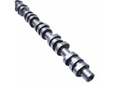
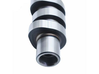
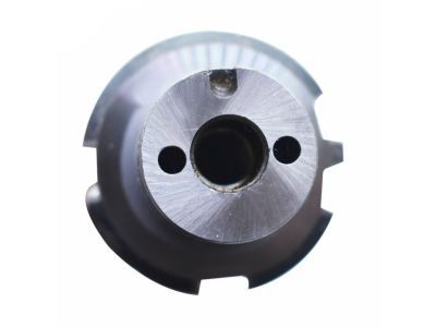
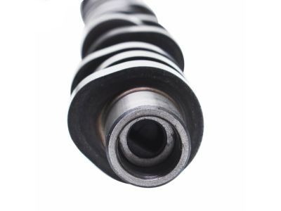
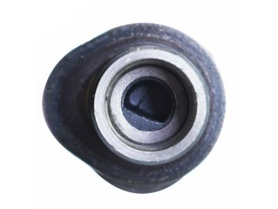
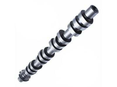
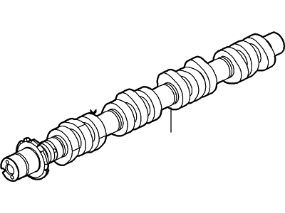
Mercury 5L1Z-6250-AA Camshaft

2006-2008 Mercury Mountaineer 5L1Z6250AA

Customer Questions & Expert Answers (10)
Ford 5L1Z-6250-AA Camshaft
  • Part Description
    Camshaft
  • Position
    Driver Side
  • Replaced By
    5L1Z-6250-E
  • Manufacturer
    Ford
Make sure this part fits
$153.90 MSRP: $225.00
You Save: $71.10 (32%)
Ships in 1-3 Business Days
1
ADD TO CART
  • Related Parts
  • Product Specifications
  • Vehicle Fitment
  • Customer Questions & Expert Answers
  • Product Specifications

    BrandGenuine Mercury
    Manufacturer Part Number5L1Z-6250-AA, 5L1Z6250AA
    Part DescriptionCamshaft
    Manufacturer NoteDo Not Install In Reman Head With Bearing Inserts. If Cam Requires Replacement In Reman Head, New Head Is Reqd
    Item Dimensions3.4 x 3.4 x 21.8 inches
    Item Weight7.30 Pounds
    PositionDriver Side
    ConditionNew
    Fitment TypeDirect Replacement
    ManufacturerFord
    SKU5L1Z-6250-AA
    WarrantyThis genuine Ford part is guaranteed by Ford's factory warranty.
    Shipping & ReturnShipping Policy Return Policy
    Warning: California’s Proposition 65
  • Vehicle Fitment

    Year Make Model Engine Important vehicle option details
    2006-2008 Mercury Mountaineer8 Cyl 4.6L5-Speed Automatic Transmission 5R55S, 5-Speed Automatic Transmission 5R55W, 5-Speed Manual Transmission (M5R4), 6-Speed Automatic Transmission (6R80), 6-Speed Automatic Transmission 6R60, Four-Wheel Drive (Full Time) (Left Hand Drive), Four-Wheel Drive (Part Time) (Left Hand Drive), Four-Wheel Drive (Part Time) (Right Hand Drive), Left Hand Drive, Rear-Wheel Drive (Left Hand Drive)
  • Customer Questions & Expert Answers

    Q:
    Will these fit my car and if not which part will? Thank you. Posted by FordPartsGiant Specialist
    A:
    You can Select Your Vehicle to check if 5L1Z-6250-AA fits your vehicle.
    Posted by FordPartsGiant Specialist
    Q:
    How to remove and install Camshaft in V6 engine on Ford Mustang? Posted by Customer
    A:
    It is a very complex structure to work with and in particularly with the timing chains, only special tools designed for working on the 3.7L engine will suffice to undertake the task in order not to damage the engine. As an interference engine the timing chain if snapped this can lead to valve and possibly piston damage, it requires cylinder head removal. Due to the complexity of the timing system, a slight mistake can cause a lot of damage to the engine, thus, they should only be done by highly qualified personnel, and it is always good to cross check all the repairs done before starting the engine. Two special camshaft holding tools (manufacturer tool no. 303-1248) are required for the operations described). Before camshafts can be taken out, the valve clearance should be checked, at the same time the primary timing chain and camshaft VCT unit is to be taken out. To examine hydraulic lifters, one has to first remove camshaft caps while paying attention to their arrangement; after this, camshafts can be pulled out of the cylinder head. Lifters should be removed with magnet and the same placed in a container marked for assembly after the end of the test. After camshaft removal they should be cleaned and checked for wear or damage before Guage dimensions are taken to determine if they meet their specifications. If one finds the camshaft lobes intact and in good condition then it is possible to reuse them. Proper alignment of the crankshaft before application of lubricants on the lifters and camshafts as well as re-fixing the seals that go well with lifters and camshafts. This is done by tightening the camshaft bearing caps in the correct order and also by further adjustments of the valve clearance. Before going ahead with the VCT units and the primary timing chain, the camshaft holding tools must be fitted. The same is true for the 4.0L engine procedure which is quite elaborate and involves the use of special tools and engine pull out. It entails such tasks as, dismantling involving taking off of valve covers, measuring of camshaft end play, loosening of bearing cap screws, and making sure all parts are replaced in their respective positions. During inspection, horn and camshaft journals and lobes are inspected for signs of wear and when this is done, camshaft journals and lobes are measured in relation to their specified measurements and replaced if not as required. Oil clearance checks are made with the use of Plastigage, and should the clearances be large, then the cylinder head has to be replaced. If any had been taken out, they had to be replaced on the same position and then lubricated before having the camshaft caps tightened to the recommended torque setting.
    Posted by FordPartsGiant Specialist
    Q:
    How do you remove and install Camshaft Bearing and Camshaft in V6 engine on Lincoln Navigator? Posted by Customer
    A:
    To inspect camshaft lobe lift and measure wear, it is required to have the rocker arms out of the way while the pushrods remain in. Turn the engine until the number one piston is at top dead centre of the compression stroke: install a dial indicator on the cylinder head with its plunger touching the first rocker arm. Aim the needle of the dial indicator at the lowest point of the cam lobe and zero it and slowly turn the crankshaft until the needle deflects in the opposite direction, this gives the maximum cam lobe lift. Note this measurement and move the piston to TDC then follow the same process on the other valves while making sure that every piston is at TDC. After making the above checks, another check can be made to compare it with the specified value; if the lobe lift is below the specified value then cam lobe wear has taken place and this is a sign that you are going to need a new camshaft. For removal, pull out the pushrods and their lifters, timing chain and the sprocket from the camshaft; measure the end play with a dial indicator. In case the play is beyond the measures allowed by the specifications, it is advisable to fit a new thrust plate when installing the new assembly. Withdraw the camshaft slowly, gently to prevent bending the bearings that are sometimes so small that they can hardly be seen. You should check the camshaft for wear, pitting or any form of damage once it has been removed; if the journals are badly worn, both the camshaft and bearings will have to be taken out and this will call for the services of an expert. Check the bearing journals for signs of wear by using a micrometer and examine the lobes for any sign of discoloration or damage, if the camshaft has not been badly abused, it may be reused. The procedure for the balance shaft is similar to the one described above; the thrust plate bolts should be loosened, and the shaft should be guided out; still, it is necessary to remember that any signs of wearing of the bearings might only be seen by a machine shop. The journals ought to be lubricated any time installation is being performed again and the keyway should sit right as it should with the gear. It is also recommended that the camshaft bearing journals and lobes should be lubricated before placing the camshaft into the engine; also aligning the balance shaft gear. Coat the thrust plate with grease and while doing this place it in its proper position, To put it in the right place for reassembly the process is done in the reverse to that of the removal process. Last but not the least; replace the oil as well as oil filter before turning on the engine.
    Posted by FordPartsGiant Specialist
    Q:
    How to remove and install the camshaft in V8 engine on Ford Expedition? Posted by Customer
    A:
    In the process of disassembling the engine to replace the bearing, one has to unscrew the valve covers, timing chain cover, remove the timing chains and the camshaft sprockets with their spacers, make sure not to confuse the sprockets labeled as RB-right bank and LB-left bank since they should be replaced in the identical manner. Regarding 5.4L 4V engines, apply pressure using a C-clamp on the secondary timing chain tensioner so that you can fit pins to immobilize it before removal, do the same with the other cylinder head. The seat of the plunger is triggered by spring so be careful when putting the insertion tubing through the end of the assembly. Using the camshaft sprocket bolt and the large washer to immobilise the intake camshaft, shift both the camshaft sprockets and their spacers with the secondary chain. Check the thrust clearance of the camshaft(s) with the dial indicator and use new thrust plates and bearing caps if the clearance is beyond the standard limit. The camshaft journal caps extra design to indicate their location for correct installation on the camshaft caps cluster. Do not rotate the crankshaft in various directions with the timing chains removed to prevent valve-to-piston contact. Proceed and unwind the bearing cap bolts slowly, then turn the caps in as well as raise the camshaft off the cylinder head without swapping the parts. Externally, look for any scratches or wear on the cam lobes and bearing journals, and then, by means of micrometers, take measurements of the diameter of each camshaft journal, and camshaft lobe lift, and replace the camshaft if there are large variations. The check Plastigage for wear and clearance of each camshaft journal, clean the oil feed tube and reservoir of the timing chain tensioner before the installation of the cam caps. If lash adjusters or camshaft followers were removed, replace them in the same positions, use grease or camshaft installation lube on the camshaft lobe and bearing journals before placing the camshaft(s). Replace the lost camshaft caps and tighten the bolts gradually so as to ensure the camshafts are correctly positioned at TDC with the timing chain and cover reinstalled in a reverse process of what was used to remove them.
    Posted by FordPartsGiant Specialist
    Q:
    What is the procedure for tightening the camshaft caps for the 2009 Ford Mustang? Posted by Customer
    A:
    Install the camshaft caps in the correct locations, loosely install all the bolts, and then tighten the bolts in 1/4-turn increments following the correct bolt-tightening sequence.
    Posted by FordPartsGiant Specialist
    Q:
    What caution should be taken when handling the tensioner for the 1998 Lincoln Navigator? Posted by Customer
    A:
    The plunger is spring-loaded; do not remove the tensioner without pinning it, or it could drop out and be damaged.
    Posted by FordPartsGiant Specialist
    Q:
    How should the checks be conducted for the remaining valves for the 2009 Ford Expedition? Posted by Customer
    A:
    Each piston must be at TDC on the compression stroke, and the checks should follow the firing order sequence.
    Posted by FordPartsGiant Specialist
    Q:
    What are the steps for the 2011 Ford F-150? Posted by Customer
    A:
    15. Remove the VCT assembly from the front end of each camshaft. 16. Hold the flats of the camshaft with a wrench while using a ratchet and socket to remove the VCT mounting bolts. 17. On 5.0L engines, remove the larger camshaft cap first, then loosen and remove the remainder of the bearing cap bolts. 18. On 6.2L engines, loosen and remove the camshaft bearing cap bolts in the reverse of the tightening sequence. 19. Lift the camshafts out of their bearing saddles and set them aside. 20. Keep the camshafts clean and mark them with paint to indicate left or right and intake or exhaust.
    Posted by FordPartsGiant Specialist
    See expert answers on similar Camshaft
    Q:
    What are the initial steps to prepare for the camshaft lobe lift check for the 2010 Ford F-150? Posted by Customer
    A:
    The initial steps include removing the valve covers and rocker arms while leaving the pushrods in place, and positioning the number one piston at TDC on the compression stroke.
    Posted by FordPartsGiant Specialist
    Q:
    What should be done after installing the camshaft bearing caps for the 2010 Ford F-150? Posted by Customer
    A:
    Recheck the valve clearances since the crankshaft is in the neutral position, allowing the camshafts to be turned without the valves contacting the pistons.
    Posted by FordPartsGiant Specialist
    If you have any questions about this product, please don't hesitate to ask us. We will be happy to help you!

Genuine Ford Part 5L1Z-6250-AA, the Right Choice

To ensure reliability, purchase Ford part # 5L1Z-6250-AA Camshaft. It is sometimes referred to as Mercury Camshaft. In terms of quality and longevity, OEM parts are top-tier. This is because they are made according to Ford's demanding factory specifications and go through strict quality control. This part fits specific Mercury Mountaineer models.

FordPartsGiant.com is a leading supplier of genuine Ford parts and accessories such as Ford 5L1Z6250AA Camshaft. On our platform, we provide genuine Ford parts at incredible prices while ensuring top-tier quality. Feel at ease shopping with us, knowing our parts have a hassle-free return policy and rapid delivery service. For detailed Mercury parts information, click here.

Why choose Ford Parts Giant

  • Dedicated Service

    Your complete satisfaction is our #1 goal

  • Lowest Prices

    Best deals on genuine OE parts from dealerships

  • Fast Delivery

    Orders are processed and delivered promptly