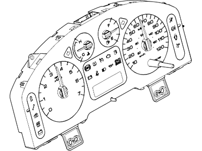
More so, this procedure proves hard for the home mechanic due to concealed fasteners and the many awkward positions and restricted visibility, electrical connectors that have to be labelled and removed. Thus, it can only be recommended for those who are very experienced in handling the various aspects of a do-it-yourself project. For a better access, first, you need to disconnect the steering wheel, all the trim panels located on the dashboard, the glove box, air conditioning and heater control assembly, the instrument cluster and the radio, right lower insulator of the instrument panel, and the front seats. Next, it is necessary to remove the left and right A-pillar trim panels and release the tether of the two, finally, to remove the front door opening sill and kickpanels. Remove the left kick panel, as well as the bulk head electrical connector, the aerial cable and for communication systems the satellite aerial if fitted. Take off the cowl panels and the firewall to instrument panel bolts on the side of the engine compartment. Undo the electrical connectors of the PCM, and then unbolst and remove the PCM and the mounting bracket. In the glove box area, remove all power connectors for the air conditioning system, wire harness in the floor at the forward area of the front seats. Remove any of the remaining wiring connectors from the circuitry between the vehicle and the instrument panel. The strut tower cross brace needs to be removed so do that in the engine compartment. Liberate the upper end of the lower steering column shaft by unbending its mating to the upper STEERlng column shaft, then remove the upper STEERling column pinch bolt, and pry the upper stearing column shaft away from the lower one as the bottom of the steering column is being pulled apart, discard the old pinch bolt and replace it with a new one as you reconstruct the assembly. Take the screws which hold the hood release handle in place and set a side the handle. If so endued, disconnect the aspirator hose from the heater core/evaporator core housing if fitted. Disengage the shift lever cable and take out it from the clips which hold the cable. Disconnect the electrical connectors, and then take out the centre console together with its support. Pull back the carpet and remove the plastic pushpin-type retainers and then take off the electrical connector of the Restraints Control Module. Open both a side and left side in the instrument panel brace to floor bolts together, and left side instrument panel mounting bolts from inside driver door, but some of the early models will have the Torx head bolt, which cannot be wholly undone. Disconnect the right side instrument panel bolts these are behind the door opening of the passenger's side, an assistant is supposed to hold the instrument panel to avoid it falling off when the bolts are being undone. With help, slowly retract the instrument panel and then check wires/hard wires of any missed electrical connectors. Installation is done in a reverse order of what was done for removal to guarantee that the A pillar trim panels are fixed correctly with their tethers as well as the clips.
Posted by FordPartsGiant Specialist 


