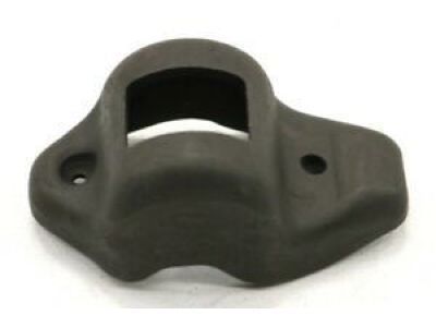
Detach the valve cover(s) from the cylinder head(s). Starting at the front of one cylinder head, remove the rocker arm fulcrum bolts, which may not need to be completely removed; loosen them several turns and check if the rocker arms can be pivoted out of the way for pushrod removal. Store the bolts separately in marked containers to ensure they are reinstalled in their original locations. If only the pushrods are being removed, loosen each bolt just enough to allow the rocker arms to be rotated aside for pushrod extraction. Lift off the rocker arms, fulcrums, and fulcrum guides if used, and store them in marked containers with the bolts. Remove the pushrods and store them separately to avoid mixing during installation, using a perforated cardboard box to ensure they are reinstalled in their original locations, noting the label indicating the front of the engine. Check each rocker arm for wear, cracks, and other damage, especially where the pushrods and valve stems contact the rocker arm faces, ensuring the hole at the pushrod end of each rocker arm is open. Inspect the rocker arm pivot area and fulcrum for wear, cracks, and galling; replace worn or damaged rocker arms and fulcrums with new ones. Inspect the pushrods for cracks and excessive wear at the ends, rolling each across a piece of plate glass to check for bending. Before tightening the rocker arm bolts, ensure both lifters for each cylinder are on the base circle of the cam lobe with both valves closed. Lubricate the lower end of each pushrod with clean engine oil or moly-base grease and install them in their original locations, ensuring each pushrod seats completely in the lifter. Apply moly-base grease to the ends of the valve stems and the upper ends of the pushrods before positioning the rocker arms, fulcrums, and guides, and also to the fulcrums to prevent damage to the mating surfaces before engine oil pressure builds up. Set the rocker arms and guides in place, then install the fulcrums and bolts. Adjustment is typically needed only when valve train components have been replaced or valves have been ground significantly. Set the number one piston at Top Dead Center (TDC) on the compression stroke, which is position 1 for checking and adjusting valve clearances. In this position, check the intake valves 1, 3, and 6, and the exhaust valves 1, 2, and 4, with the arrangement of intake and exhaust valves being left side - E-I-E-1-E-I and right side - 1-E-1-E+E. Using a Ford lifter bleed-down tool or equivalent, press on each rocker arm until the lifter leaks down completely, then check the clearance between the valve stem and rocker arm with a feeler gauge, comparing it to the specifications and recording the results. Rotate the crankshaft to position 2 and check the intake valves 2, 4, and 5, and the exhaust valves 3, 5, and 6. If the clearances are within specification, install the rocker arm covers. The clearance can be adjusted by using different length pushrods available from your dealer; if there isn't enough clearance, use a shorter pushrod, and if there is too much clearance, use a longer one.
Posted by FordPartsGiant Specialist 

