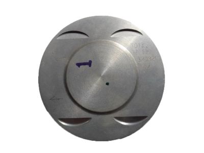
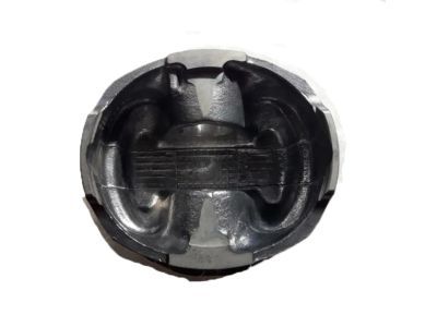
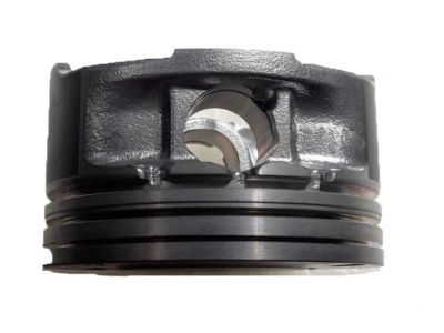
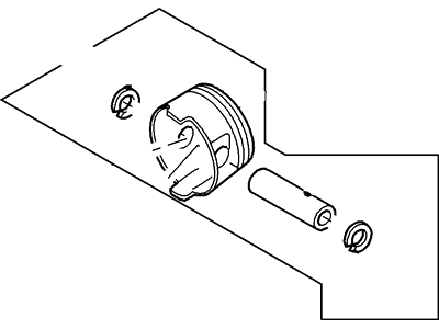
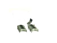
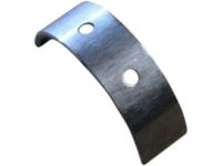
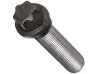
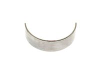
Before finally dismantling the piston and connecting rods there is need to remove the cylinder head and the oil pan. In the area of 2.7L engines, the engine block skirt stiffener should be dropped in order to expose the main bearing caps and the connecting rod caps; for 3.5L engines, the main bearing cap support brace must also be set aside. Feel with a fingernail along the cylinder walls above the rings' travel range; if there are any ridges, a ridge reamer erases them to avoid piston breakage. Once you have eliminated these ridges, undercover the crankshaft, and for four-cylinder engines, the balance shaft assembly has to be unwired. When dismantling the main bearing caps or / and the connecting rods it is necessary to measure the endplay of the connecting rod with feeler gages and adjust it within the permissible range of values. Use paint to label connecting rods and caps so that they can be easily distinguished after removal of cap bolts; this should be done slowly until they can be easily unstuck and removed from the head. Lift off the no.1 connecting rod cap and the bearing insert without letting go of the insert then push out the connecting rod / piston assembly upwards through the top end of the engine if needed with the help of some wooden or plastic hammer handle. Do this for the other cylinders and then take out the connecting rod caps and the bearing inserts that were fitted onto the other rods, reinstall the caps and place the old insert back again so as to prevent bearing's surface from getting spoiled. Subsequently, the pistons and the connecting rods are in a position to be examined and refurbished. When replacing the piston rings, check the ring end gaps as well as the piston ring side clearance for the new piston rings to be used. Arrange the piston/connecting rod assemblies and new ring sets in sequence so that they could be fitted as a set. Place the top ring in the first cylinder by aligning mounting dowels on the block with pin holes in the ring; the ring must be square to the cylinder walls; the end gap should be within 0.006 in. If the gap is small, very gradually shave the ring ends to produce a bigger gap while big gaps should be checked again to make sure that the right ring type was selected. This must be done for each ring in all cylinders and then set the rings onto the pistons with the Oil Control Ring first and followed by the second then the top ring with the identification mark in the correct position. Prior to the installation, the cylinder walls should be free from rust or debris, the top edges of the cylinder should be deburred if necessary and the crankshaft is to be fitted from below. Take off the cap of the number one connecting rod, degrease the bearing areas and set the new upper bearing insert into the cap without using any lubricant. Align the gaps of the piston rings at the 90-degree angles, partway through apply the oil its the piston together with rings, use the piston ring compressor while tightening. Place the piston/connecting rod assembly into the cylinder bore, so that the connecting rod is parallel to the crankshaft journal. Following bolt-up, measure the connecting rod bearing oil clearance by the appearance of the crushed Plastigage to the specified width. If the clearance is deemed improper, check clean and recheck the journal diameter before the bearing inserts thought to be new. After removing the Plastigage, use an appropriate thickness of grease on the bearing areas, re-insert the connecting-rod and tighten the rod cap accompanied by new bolts. Perform the same for the rest of the assemblies while maintain the cleanliness and correct orientation of the components. Lastly, turn the crankshaft assembled with bearings on the fixture and examine, if any binding is there and check the connecting rod-end play and correct, if any wrong. If the engine is 2.7L, the engine block skirt stiffener can also be installed, if it is 3.5L, the main bearing cap support brace must be installed, and if it is 2.0L, 2.3L, or 2.5L four-cylinder, the balance shaft assembly must also be installed.
Posted by FordPartsGiant Specialist 

