Make sure this part fits

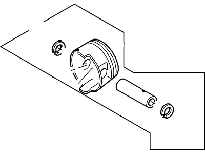
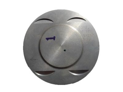
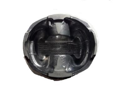
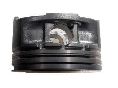
Mercury 3W4Z-6108-A Piston And Pin Assembly

2005-2011 Mercury 3W4Z6108A

Customer Questions & Expert Answers (5)
Ford 3W4Z-6108-A Piston And Pin Assembly
  • Part Description
    Piston And Pin Assy
  • Base No.
    6100
  • Replaces
    XW4Z-6100-A
  • Manufacturer
    Ford
Make sure this part fits
$10.14 MSRP: $14.45
You Save: $4.31 (30%)
Ships in 1-3 Business Days
1
ADD TO CART
  • Related Parts
  • Product Specifications
  • Vehicle Fitment
  • Customer Questions & Expert Answers
  • Product Specifications

    BrandGenuine Mercury
    Base No.6100
    Manufacturer Part Number3W4Z-6108-A, 3W4Z6108A
    Part DescriptionPiston And Pin Assy
    Other NamesPiston
    Item Dimensions5.2 x 4.4 x 2.9 inches
    Item Weight1.20 Pounds
    ConditionNew
    Fitment TypeDirect Replacement
    ReplacesXW4Z-6100-A
    ManufacturerFord
    SKU3W4Z-6108-A
    WarrantyThis genuine Ford part is guaranteed by Ford's factory warranty.
    Shipping & ReturnShipping Policy Return Policy
    Warning: California’s Proposition 65
  • Vehicle Fitment

    Year Make Model Engine Important vehicle option details
    2005-2006 Mercury Mariner6 Cyl 3.0L DOHC EFI Modular4AT CD4E, 5-Speed Manual Transmission, 5-Speed Manual Transmission - AK, Four-Wheel Drive (Full Time) (Left Hand Drive), Four-Wheel Drive (Right Hand Drive), Left Hand Drive, Two-Wheel Drive (Left Hand Drive), Two-Wheel Drive (Right Hand Drive)
    2006-2011 Mercury Milan6 Cyl 3.0L DOHC EFI, 6 Cyl 3.0L OHC Duratec5-Speed Automatic Transmission Mazda FNR5, 5-Speed Manual Transmission (G5M), 6-Speed Automatic Transaxle - AWF21, 6-Speed Automatic Transmission 6F Mid-Range, 6-Speed Manual Transmission Mazda G6M, CVT Auto Trans Powersplit Elec, Four-Wheel Drive (Full Time) (Left Hand Drive), Front-Wheel Drive (Left Hand Drive), Left Hand Drive
    2007 Mercury Montego6 Cyl 3.0L DOHC EFI Modular6-Speed Automatic Transaxle - AWF21, CVT Select Shift Transmission, Four-Wheel Drive (Part Time) (Left Hand Drive), Front-Wheel Drive (Left Hand Drive), Left Hand Drive
  • Customer Questions & Expert Answers

    Q:
    I would like to know is this part gonna fit with my car Posted by FordPartsGiant Specialist
    A:
    You can Select Your Vehicle to check if 3W4Z-6108-A fits your vehicle.
    Posted by FordPartsGiant Specialist
    Q:
    How to remove piston and connecting rod assemblies on Ford Fusion? Posted by Customer
    A:
    Before finally dismantling the piston and connecting rods there is need to remove the cylinder head and the oil pan. In the area of 2.7L engines, the engine block skirt stiffener should be dropped in order to expose the main bearing caps and the connecting rod caps; for 3.5L engines, the main bearing cap support brace must also be set aside. Feel with a fingernail along the cylinder walls above the rings' travel range; if there are any ridges, a ridge reamer erases them to avoid piston breakage. Once you have eliminated these ridges, undercover the crankshaft, and for four-cylinder engines, the balance shaft assembly has to be unwired. When dismantling the main bearing caps or / and the connecting rods it is necessary to measure the endplay of the connecting rod with feeler gages and adjust it within the permissible range of values. Use paint to label connecting rods and caps so that they can be easily distinguished after removal of cap bolts; this should be done slowly until they can be easily unstuck and removed from the head. Lift off the no.1 connecting rod cap and the bearing insert without letting go of the insert then push out the connecting rod / piston assembly upwards through the top end of the engine if needed with the help of some wooden or plastic hammer handle. Do this for the other cylinders and then take out the connecting rod caps and the bearing inserts that were fitted onto the other rods, reinstall the caps and place the old insert back again so as to prevent bearing's surface from getting spoiled. Subsequently, the pistons and the connecting rods are in a position to be examined and refurbished. When replacing the piston rings, check the ring end gaps as well as the piston ring side clearance for the new piston rings to be used. Arrange the piston/connecting rod assemblies and new ring sets in sequence so that they could be fitted as a set. Place the top ring in the first cylinder by aligning mounting dowels on the block with pin holes in the ring; the ring must be square to the cylinder walls; the end gap should be within 0.006 in. If the gap is small, very gradually shave the ring ends to produce a bigger gap while big gaps should be checked again to make sure that the right ring type was selected. This must be done for each ring in all cylinders and then set the rings onto the pistons with the Oil Control Ring first and followed by the second then the top ring with the identification mark in the correct position. Prior to the installation, the cylinder walls should be free from rust or debris, the top edges of the cylinder should be deburred if necessary and the crankshaft is to be fitted from below. Take off the cap of the number one connecting rod, degrease the bearing areas and set the new upper bearing insert into the cap without using any lubricant. Align the gaps of the piston rings at the 90-degree angles, partway through apply the oil its the piston together with rings, use the piston ring compressor while tightening. Place the piston/connecting rod assembly into the cylinder bore, so that the connecting rod is parallel to the crankshaft journal. Following bolt-up, measure the connecting rod bearing oil clearance by the appearance of the crushed Plastigage to the specified width. If the clearance is deemed improper, check clean and recheck the journal diameter before the bearing inserts thought to be new. After removing the Plastigage, use an appropriate thickness of grease on the bearing areas, re-insert the connecting-rod and tighten the rod cap accompanied by new bolts. Perform the same for the rest of the assemblies while maintain the cleanliness and correct orientation of the components. Lastly, turn the crankshaft assembled with bearings on the fixture and examine, if any binding is there and check the connecting rod-end play and correct, if any wrong. If the engine is 2.7L, the engine block skirt stiffener can also be installed, if it is 3.5L, the main bearing cap support brace must be installed, and if it is 2.0L, 2.3L, or 2.5L four-cylinder, the balance shaft assembly must also be installed.
    Posted by FordPartsGiant Specialist
    Q:
    How to remove and install piston/connecting rod assemblies on Mercury Mariner? Posted by Customer
    A:
    Before one is able to remove those piston and connecting rod assemblies, it becomes necessary to also take off the cylinder head as well as the oil pan. First delete any ridges which should in most cases be present at upper limit of ring travel in cylinder and normally requires the use of a ridge reamer. After filing down the ridges, stand the engine on its crankshaft and check for end float of the connecting rod end using a feeler gauge and if this does not fall within prescribed limits then it may be necessary to change connecting rods. For differentiation, paint the connecting rods and caps then take off the connecting rod cap bolts and caps and along with the bearing insert. Slide out the connecting rod and piston assembly through the top of the engine while making sure that all the ridges have been evidenced. Do the above on the rest of the cylinders then put the caps on and the inserts back to cover the bearing surfaces. The below steps are the one followed when installing the piston rings: Ensure that the ring end gaps are accurate as per the set standards and if not adjust to the right limits. Start with placing the oil control ring but remember to place the middle and top rings with the proper alignment. It is necessary to remove scales on the inner surface of the cylinder and sharpen the edges of the pin before placing the new bearing inserts, and it will be the time to do this; no lubrication should be applied when races are being installed. Position which piston ring gaps should face each other at 90 degrees intervals, lubricate the piston and rings and then place the piston with the rings compressed into the cylinder. Verify the Crankshaft connecting rod bearing oil clearance with help of Plastigage and use the correct size of bearing inserts. After ensuring the clearance, use the grease on the bearing faces, then put the rod cap with new bolts and tighten them in the recommended force. Follow the same process to the other assemblies also, after ensuring that the equipment is clean and well oriented before use. Last of all, turn the crankshaft with your fingers and check for any binding and measure the connecting rod small end clearance and adjust it if unsatisfactory.
    Posted by FordPartsGiant Specialist
    Q:
    How to remove and install piston/connecting rod assemblies on Ford Escape? Posted by Customer
    A:
    Before one is able to remove those piston and connecting rod assemblies, it becomes necessary to also take off the cylinder head as well as the oil pan. First delete any ridges which should in most cases be present at upper limit of ring travel in cylinder and normally requires the use of a ridge reamer. After filing down the ridges, stand the engine on its crankshaft and check for end float of the connecting rod end using a feeler gauge and if this does not fall within prescribed limits then it may be necessary to change connecting rods. For differentiation, paint the connecting rods and caps then take off the connecting rod cap bolts and caps and along with the bearing insert. Slide out the connecting rod and piston assembly through the top of the engine while making sure that all the ridges have been evidenced. Do the above on the rest of the cylinders then put the caps on and the inserts back to cover the bearing surfaces. The below steps are the one followed when installing the piston rings: Ensure that the ring end gaps are accurate as per the set standards and if not adjust to the right limits. Start with placing the oil control ring but remember to place the middle and top rings with the proper alignment. It is necessary to remove scales on the inner surface of the cylinder and sharpen the edges of the pin before placing the new bearing inserts, and it will be the time to do this; no lubrication should be applied when races are being installed. Position which piston ring gaps should face each other at 90 degrees intervals, lubricate the piston and rings and then place the piston with the rings compressed into the cylinder. Verify the Crankshaft connecting rod bearing oil clearance with help of Plastigage and use the correct size of bearing inserts. After ensuring the clearance, use the grease on the bearing faces, then put the rod cap with new bolts and tighten them in the recommended force. Follow the same process to the other assemblies also, after ensuring that the equipment is clean and well oriented before use. Last of all, turn the crankshaft with your fingers and check for any binding and measure the connecting rod small end clearance and adjust it if unsatisfactory.
    Posted by FordPartsGiant Specialist
    Q:
    I recently purchased a part 3W4Z-6108-A from you website and although the illustration outlines that the piston comes with a piston Pin and lock the fine print states other wise which is very misleading in my opinion. Regardless of this fact, I now have a part for which I cannot find they supplement/assembly part namely the piston pin. Could you please assist in referencing or acquiring this part so that I can complete my repair? Posted by Customer: 2003 Ford Escape
    A:
    F5DE6135AA PIN F5RZ6140A RETAINERS (X2)
    Posted by FordPartsGiant Specialist 19/5/2020
    If you have any questions about this product, please don't hesitate to ask us. We will be happy to help you!

Genuine Ford Part 3W4Z-6108-A, the Right Choice

To ensure reliability, purchase Ford part # 3W4Z-6108-A Piston And Pin Assembly. It is sometimes referred to as Mercury Piston. In terms of quality and longevity, OEM parts are top-tier. This is because they are made according to Ford's demanding factory specifications and go through strict quality control. This part fits specific Mercury Mariner, Milan, Montego models.

FordPartsGiant.com is a leading supplier of genuine Ford parts and accessories such as Ford 3W4Z6108A Piston And Pin Assembly. On our platform, we provide genuine Ford parts at incredible prices while ensuring top-tier quality. Feel at ease shopping with us, knowing our parts have a hassle-free return policy and rapid delivery service. For detailed Mercury parts information, click here.

Why choose Ford Parts Giant

  • Dedicated Service

    Your complete satisfaction is our #1 goal

  • Lowest Prices

    Best deals on genuine OE parts from dealerships

  • Fast Delivery

    Orders are processed and delivered promptly