
My Garage
My Account
Cart
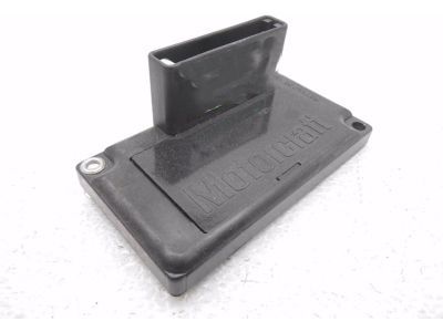
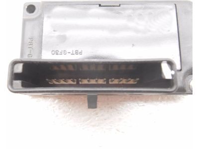
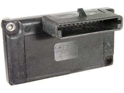
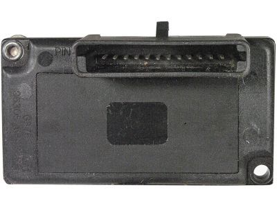
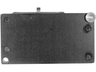
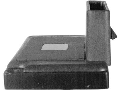
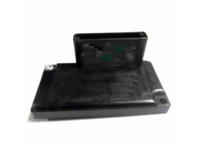
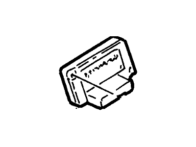
Genuine Ford Explorer Ignition Control Module
Ignition Spark Control Module- Select Vehicle by Model
- Select Vehicle by VIN
Select Vehicle by Model
orMake
Model
Year
Select Vehicle by VIN
For the most accurate results, select vehicle by your VIN (Vehicle Identification Number).
1 Ignition Control Module found
Ford Explorer Ignition Control Module
We provide a wide range of Ford Explorer Ignition Control Module at the best prices possible. If you need Ford Explorer Ignition Control Module, you can shop with confidence on our website. All our OEM parts come with a manufacturer's warranty and are delivered to your door step with a fast delivery service.
Ford Explorer Ignition Control Module Parts Questions & Experts Answers
- Q: What is the procedure for testing the Ignition Control Module and related circuits on Ford Explorer?A:This test assumes that the coil trigger signal has been checked and is not present at the ignition coil harness side connector. Special electronic test equipment is required to thoroughly test the ICM and related circuits. This test verifies the integrity of the most important circuits and assumes that, if the circuits are good the module is most likely defective. The Ignition Control Module is mounted to the radiator support behind the battery. Check for power to the ICM. Using a voltmeter, probe terminal number 8 (red wire +) and check for battery voltage. With the ignition ON (engine not running), there should be battery voltage. If battery voltage is not present, check the PCM power relay and related wiring for an open or shorted circuit. Turn the ignition OFF. Using an ohmmeter, check for continuity between terminal 9 of the ICM connector and battery ground. Continuity should exist. If no continuity exists, check the ground circuit for an open. Check the resistance of the crankshaft position (CKP) sensor on terminals number 5 and number 6. It should be between 2000 and 3000 ohms. If it isn't, check the crankshaft position sensor. Check the circuit from the ignition module to the SPOUT connector on terminal number 3 (pink wire +) for a complete circuit. Continuity should exist. If the test results are correct, replace the ignition module with a new one. Remove the battery. Disconnect the electrical connector from the ignition module. Remove the screw securing the Ignition Control Module to the radiator support. Slide the assembly up to remove the rivet from the positioning hole in the panel. Installation is the reverse of the removal.
