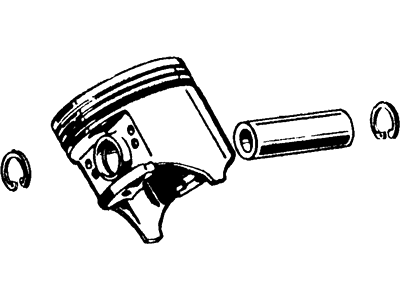
Careful should be taken to see that the cylinder walls are free from rust and the top edge of each cylinder are deburred while fixing the piston and the connecting rod, crank shaft must be fixed. Pry the connecting rod cap off, on the number one connecting rod withdraw the old bearing inserts and clean the bearing surfaces thoroughly using a clean, lint-free cloth. Before final assembly, it is advisable to clean the back side of the new upper bearing half and put it in place in the connecting rod such that the tang will slide into the correct slot without having to hammer it or damage the bearing face in the process. Clean the back side of the other bearing insert and put it into the rod cap such that the tang rests on the slot but you do not apply any lubrication. Place the gaps of the piston ring around the piston and slide a part of a plastic or rubber hose over one of the connecting rod cap bolts. Apply clean engine oil on the piston and rings, fit on the piston ring compressor; keep a 1/4-inch lip on skirt to ease the piston into the cylinder. Turn the crankshaft anticlockwise until the number one connecting rod journal coincides with bdc and lubricate the cylinder walls with engine oil. With the notch on top of the piston facing the front of the engine, gently position the piston/connecting rod assembly into number one cylinder bore so that the bottom edge of the ring compressor lays on the engine block, tap the top edge of the ring compressor. Gently strike the top of the piston lightly with a wooden or plastic hammer handle and at the same time, still holding the ring compressor down, smooth the connecting rod over the crankshaft journal and align the piston boss with the next corresponding hole in the cylinder liner. After the assembly has been installed than check the oil clearance of the connecting rod bearing before final tightening of the rod cap. Take a strip of Plastigage somewhat shorter than the bearing width of the connecting rod and place it on the number one connecting rod journal, next, clean the connecting rod cap bearing face, and remove the protective hoses before fitting the rod cap in a manner that the marked faces align. Ensure to tighten nuts to the required torque in three stages without causing rotation of the crankshaft. Take off the rod cap gently, because the movement of Plastigage may be affected, compare the width of the squashed Plastigage with that marked on the container to get the oil clearance, and check the required value. Incase the clearance is incorrect, feel for dirt or oil lying between the bearing insert and the connecting rod or any cap on it, also measure the journal diameter again. Remove any Plastigage from the rod journal and part of the bearing face gently without causing any scratch and then apply a thin film of new moly-base grease or fresh engine assembly lube on both the surfaces. Simply slide the connecting rod back into the position on the journal, detach the protective hoses, screw the rod cap back into position and finally tighten the nuts to the torque; but just like in the initial tightening of the nuts, gradually increase the torque in sequences of three. Perform the same for rest of the piston-connecting rod assembly, holding the bearing inserts and connecting rods clean, make sure to fit right piston at each cylinder with the notch in front of the engine and lubricate the piston well and then fit the ring compressor correctly over it. After all assemblies are installed, take the crankshaft and try to rotate it by hand to check for excessive binding; finally, check the con rod end float by feeling the movement at the big end, the measured endfloat should be correct; if new con rods or a new crankshaft was assembled to the engine, the endfloat may require adjustment, by taking the rods to an automotive machine shop for reboring.
Posted by FordPartsGiant Specialist 

