×
- Live Chat
- 1-888-788-9341


My Garage
My Account
Cart
Genuine Mercury Lynx Ignition Control Module
Ignition Spark Control Module- Select Vehicle by Model
- Select Vehicle by VIN
Select Vehicle by Model
orMake
Model
Year
Select Vehicle by VIN
For the most accurate results, select vehicle by your VIN (Vehicle Identification Number).
4 Ignition Control Modules found
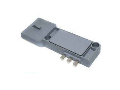
Mercury Lynx Module - Ignition
Part Number: E43Z-12A297-A$60.50 MSRP: $100.00You Save: $39.50 (40%)Ships in 1-2 Business DaysMercury Lynx Module Assembly - Ignition
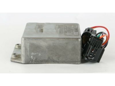
Part Number: D9VZ-12A199-A$57.80 MSRP: $93.64You Save: $35.84 (39%)Ships in 1-2 Business DaysMercury Lynx Module Ignition
Part Number: E9RZ12A297A$30.01 MSRP: $41.01You Save: $11.00 (27%)Ships in 1-2 Business DaysMercury Lynx MODULE - IGNITION
Part Number: E3FZ12A297B$32.26 MSRP: $44.08You Save: $11.82 (27%)Ships in 1-2 Business Days
Mercury Lynx Ignition Control Module
We provide a wide range of Mercury Lynx Ignition Control Module at the best prices possible. If you need Mercury Lynx Ignition Control Module, you can shop with confidence on our website. All our OEM parts come with a manufacturer's warranty and are delivered to your door step with a fast delivery service.
Mercury Lynx Ignition Control Module Parts Questions & Experts Answers
- Q: How do you test and replace the ignition module on Mercury Lynx?A: Caution is advised as the ignition control module is a delicate and relatively expensive electronic component, requiring tests to be performed with the appropriate equipment by knowledgeable individuals. Failure to adhere to the outlined procedures may lead to damage to the module or other electronic devices, including the EEC-IV microprocessor in TFI vehicles. All devices under computer control are protected by a Federally mandated extended warranty, so consulting a dealer before attempting self-diagnosis is recommended. To check the Duraspark II system ignition control module voltage, turn off the ignition switch, insert a small straight pin into the red module wire without grounding it, attach the negative lead of a voltmeter to the distributor base, measure battery voltage, and then attach the positive lead to the pin in the red module wire with the ignition switch in the Run position. If the measured voltage is less than 90 percent of the battery voltage, inspect the wiring harness and ignition switch for wear and damage. For the ignition control module wiring harness, attach one lead of an ohmmeter to the distributor base and check the resistance between the wiring harness terminals mating with the black and purple module wires. If the resistance is greater than the specified value, the ignition control module-to-distributor stator wiring harness resistance is normal; otherwise, inspect the wiring harness. Unplug and inspect the four-wire ignition control module electrical connector and the ignition coil connector, then measure the resistance between the TACH terminal of the ignition coil connector and ground. If the resistance is greater than one ohm, replace the ignition control module; if less, inspect the wiring harness. For the ground circuit, insert a small straight pin into the black module wire, attach the negative lead of a voltmeter to the distributor base, and measure the voltage at the black wire. If the voltage is greater than 0.5 volt, check the distributor ground circuit; if less, replace the ignition control module. Unplug the electrical connector from the distributor and inspect it, then measure the resistance in the distributor ground circuit. If the resistance is less than one ohm, the circuit is okay; if greater, check the ground screw in the distributor. For the TFI-I system, remove the distributor and ignition control module, check the condition of the distributor ground screw, stator wires, and connector terminals, and connect an ohmmeter between the stator terminals. For the TFI-IV system, unplug the wiring harness connector from the ignition control module, inspect it, and check for spark using a calibrated spark tester. If there is no spark, proceed to the distributor/TFI-IV module check. If spark is present, the issue may lie with the inferred mileage sensor or the EEC-IV electronic control module, which requires professional diagnosis. For models from 1984 to 1987, purchase a new ignition control module before performing checks, as the process may necessitate a new module. For models from 1987 to 1990, measure resistance between the ignition control module terminals in various ignition switch positions; if resistance is as listed, the module is good, and the stator is defective. For module replacement in the Duraspark II system, detach the cable from the negative terminal of the battery, unplug the appropriate connectors, remove the mounting screws, and detach the module, ensuring installation is the reverse of removal. For TFI and TFI-IV systems, remove the distributor, unscrew the module mounting screws, and disconnect the spade connectors from the stator connector, applying silicone dielectric grease to the back side of the module before installation.


